


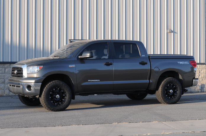
Lots of people love lifting their trucks and adding huge tires. It looks great, but it destroys much of its practicality, specifically when used as a daily driver or tow vehicle. We were interested in a conservative approach to making our truck unique and different from a typical stock vehicle.
We knew we wanted something more aggressive looking that wouldn’t interfere with towing ability or practicality. Unsure of the exact route to take, we called our friends at www.summitracing.com. After discussing the many options they have available, we ordered a set of Bilstein 5100 series shock absorbers that would serve a dual purpose for our install.
First, they would be an upgrade from the factory Bilstein shock package provided on the TRD-package Tundras. Second, and more important, they would provide us with up to 2.5 inches of lift on the front end of the truck. This would be accomplished by a slight redesigning of the front shock and spring perch to lift the vehicle 2.5 inches. The front kit also provides three different lift heights at the front. You could choose from .75, 1.5, or 2.5 inches of lift.
At the rear, Bilstein lengthened the shocks to compliment trucks with a slight lift. Summit Racing suggested the Pro Comp 1-inch lifting blocks, which are simple to install between the axle and leaf spring, providing 1 inch of rear lift, which levels out the truck nicely.
We also added a set of Toyo 325-60-18 Open Country A/T II all terrain-tires mounted to a set of 18 x 9 KMC XD Series Hoss wheels. Now, lets get on with the installation.
Rear Shocks
Your vehicle will need a proper alignment when you are finished installing four shocks. Have that performed right after the work is done and before driving any significant distance.
We chose to start at the rear of the truck because it was the easiest. We will be changing the rear shocks and installing the 1-inch lift blocks at the same time. On a scale of 1-to-10 with 10 being very advanced, I would rate this part of the build a 4.
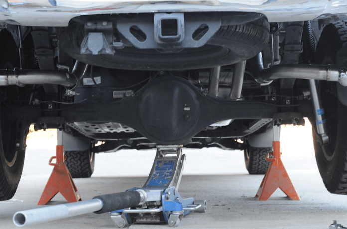


Before we finish installing the new rear shocks, we must install the lifting blocks. If you install the shocks right now, you wouldn’t be able to lower the axle away from the springs to install the lifting block between the two.
Remove the nuts from the U-bolts you already loosened on the axle and spring. Replace them with the new U-bolts supplied in the Pro Comp lifting block kit. Then lower the jack so the axle drops enough away from the spring to slide the lifting block in between.


Front Shocks
I am going to explain a “trick” way of installing your new front shocks without the use of a spring compressor because I didn’t have one large enough for the springs on the Tundra. Feel free to use this same method. It’s effective and safe for completing the job in a timely fashion. You will be using the jack on the lower control arm to extend and compress the spring so everything goes together smoothly.
On the road, the new Bilstein shocks feel firmer than the stock shocks without being harsh or annoying. They’re a fantastic addition to the vehicle, considering they also provided the subtle lift we were looking for.
On a scale of 1-10 with 10 being very advanced, I would rate this portion of the build a 6, because it’s a fairly complicated process, but can be completed with patience and thinking things through. Just stick to the very specific order or you will experience problems with this part of the install.


Jack up the lower control arm to remove pressure from the shock assembly. Break loose the lower shock bolt and then move to the upper shock bolt, which you already broke loose earlier. Slowly remove the upper shock nut until it’s free.
Slowly lower the jack and you’ll notice the top of the shock rod lowering through the upper spring hat as the spring decompresses. Once the spring is fully extended, you can remove the lower shock bolt and pull the shock/spring out of the mounting location. Be patient and think this part through, because it can be a pain getting it out and back in, and you don’t want to hurt the brake line or sensor near the shock. Pay attention to the order of the washers and bushings again at the top of the shock. It should be nut, washer, bushing, vehicle, bushing, washer from top to bottom.


Wheels and Tires
We turned to the folks at Toyo Tires, who suggested the new Open Country A/T II. We use the truck primarily for towing, but we still wanted the option of going off road. The new tire from Toyo has an aggressive tread design, while still providing a quiet ride on the road and amazing on- and off-road traction. Couple that with Toyo’s No Regrets® 45-day, 500-mile trial offer and its industry-leading 65,000 mile warranty, this tire simply can’t be beat — and sales have been brisk since its release.
After putting around 8,000 miles on the tires, I can report that they are the most impressive all terrain tire I’ve ever driven on. The traction and handling these tires produce are simply amazing, from snow and sand, to rain and mud, and anything in between.


Tools needed:
- Large breaker bar
- Torque wrench
- Rubber mallet
- Floor jack
- Pair of jack stands
- 12 mm socket and open ended wrench
- 14 mm socket and open ended wrench
- 19 mm socket and open ended wrench
- 22 mm or 7/8-inch socket wrench
- 24 mm or 15/16-inch socket wrench
- Small crescent wrench
Torque Specs:
- Two 22mm lower control arm bolts at ball joint connection. 221 ft./ lbs.
- 22 mm lower shock nut. 144 ft./ lbs.
- 19mm front sway bar lower bolt. 89 ft./ lbs.
- Lower control arm eccentric cam bolts. 100 ft./ lbs.
- Lug nuts for alloy wheels. 97 ft./ lbs. or 154 ft./ lbs. for steel wheels.


