


Keeping a C5 Corvette cool on a racetrack in 100-degree heat isn’t easy. Just ask NASA Utah’s George Smith, who had been trying different radiators and adding duct work to get as much air as possible to the radiator in his car to keep it cool. Still, the car would run at 230 to 235 degrees Fahrenheit on hot summer days, which saps power output and can shorten engine life.
Because the top of the radiator in a C5 Corvette is angled forward, the path the air must take isn’t straight. A skilled fabricator, Smith built an air intake for the radiator, and mounted it at the bottom of the front bumper fascia, above the splitter. The intake was as wide as the radiator, but it still wouldn’t keep the car cool, even after trying a few different radiators. By that point, Smith was on a first-name basis with the folks at C&R Radiators and Ron Davis Racing.
“The biggest problem I’ve got is that I run the car at 4,500 feet out here at Miller (Utah Motorsports Campus), so it’s thin air. And it’s an LS7, so it’s got a pretty long stroke, so you get a lot of heat, a lot mechanical energy going on,” Smith said. “Keeping the car cool had been a problem for several years. On a hot day, it was really hard to keep the engine temps in line with what I’m comfortable with.”
The problem certainly wasn’t workmanship. Smith’s ductwork looked as though it were built in a professional fab shop, not at home in his garage. Then, one weekend at a race at his home track, he was talking to a friend about the car’s cooling issues when a stranger walked into his pits.
“He was a very smart engineer and he looked at what I was doing, and said I had a couple of fundamental problems,” Smith said.
The stranger who wandered into Smith’s pit space was Eric Ahlstrom, an engineer who does aerodynamic work for a company that makes rockets, among other things — and that makes him a rocket scientist. Ahlstrom also has done aerodynamics development work for pylon racing aircraft and Steve Fossett’s landspeed racer before Fossett died in a plane crash in 2007.
Ahlstrom pointed out that getting air to flow from a relatively small opening to the large surface area of an angled radiator depends on smooth flowing surfaces. The ductwork Smith made had some hard angles in it, which were creating vortexes and hampering flow to the top of the radiator.


“There’s a formula for it. The fancy name for it is gradient optimization,” Ahlstrom said. “What that means is the pressure and velocity and vector change of air flow in any duct should be as gradual as possible. In other words, we know it’s got to be this direction and air speed at point A and it’s going to be this direction at air speed desired at, you know, point C, then between those two we have to draw as smooth a line as possible. And literally, that’s what it is. To do that, the walls of the duct have to be sinusoidal. They have to look like a sine wave.”


Ahlstrom sketched out for Smith a cross section of what the duct should look like. In place of hard angles, Ahlstrom drew gently angled panels. With smooth contours in the duct work, the air clings to and is directed by the surface rather than tumble off it and create a vortex that hampers good air flow. The biggest challenge, Ahlstrom said, was getting air flow up to the top of the radiator.
Ahlstrom suggested a horizontal diffuser inside the duct work to direct air flow to the upper part of the radiator, but to make the curve gentle enough that the air below it wouldn’t delaminate, so that it would it follow the curvature of that baffle. If you put a baffle in it and make it too sharp, the air flow will delaminate on the lower part and create a vortex where the radiator isn’t getting any air in the middle. The diffuser becomes a blockage for the air to the center part of the radiator.
“I had worked under theory that if you cram enough air in there you’ll create enough high pressure that the air has to go through all parts of the radiator, but in actuality, a lot of the radiator wasn’t getting much air flow through it,” Smith said. “The air’s always going to take the path of least resistance. So it was going through the bottom of the radiator pretty efficiently and not much was going through the top at all.”
Here we begin to understand why the car wasn’t cooling sufficiently. Ahlstrom also told Smith that the air the new duct work would direct to the radiator needed an efficient place to exit behind the radiator. He explained and sketched out a “chimney” sealed to the hood that would extract air from behind the radiator up and out of the engine compartment.
“There’s just as much drag and efficiency to be found in optimizing the exhaust duct of a cooler as there is optimizing the inlet,” Ahlstrom said. “Exactly the same principles apply.”
To test whether air was flowing out of the hood, Ahlstrom suggested he tape yarn tufts to it and film it at speed with a GoPro. It’s the easiest and most accurate way to determine airflow.
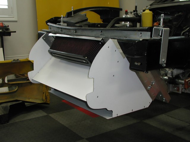
Armed with all this new knowledge, Smith went back to his garage and set to work revising his radiator air intake and exit ducts. Working first with poster board to determine shape and fit, and then as a pattern for the new aluminum panels, Smith redesigned the intake and added a “chimney” that would mate to a new hood he purchased from Black Dog Racing, which it had left over from its days racing a C5 in World Challenge.
The hood itself has a raised lip at the front of the openings to create turbulence, which creates low pressure and actually draws the air out of the engine compartment or the chimney, and that helps the air flow out from behind the radiator more efficiently and adds about 30 pounds of downforce, too.
“The most important thing I noticed is that now even on the hottest days — it can be over 100 degrees at Miller — the car doesn’t go over 210 degrees,” Smith said. “By understanding how air flow works, understanding that air clings to a curved surface, and in designing the air box to have those contoured surfaces and putting them in the diffuser with a nice gentle curve upward, I got a lot more air to a lot more of the surface area of the radiator and then made it much easier for the air to exit out the other side.”

Smith also fashioned a system to feed cold air to the intake behind the front bumper fascia. The two air intake systems are completely separated. What’s even more interesting about the system is that Smith fabricated the chimney so he could install and remove it without having to disconnect any air intake, oil or coolant plumbing. If you look closely, you can get an idea of how it all goes together.
“What you’re seeing there isn’t my first attempt,” Smith said. “It took a little figuring out how to do it, because I didn’t want to be disconnecting water lines and hoses every time I work on the car.”
Smith saves all the patterns he makes in case of crash damage. He has since shared the patterns with a couple of other C5 drivers who were having similar cooling issues.
“These are very simple rules that anyone can follow,” Ahlstrom said. “I’m really, really happy that you called. I have a problem in my business where people they use a solution of mine, they tend to take credit for it. All I gave George was advice, and he was not only able to follow it, which was very rewarding for me that he had good results, but that he appreciated my time and told you about it.”
It might not seem like rocket science, but then again, maybe it is.


