Stock Miatas run rich at high rpm. Installing an adjustable fuel-pressure regulator can add power, decrease fuel consumption — and maybe keep the bumper a bit cleaner.
Horsepower doesn’t come cheaply or easily in Spec Miata. Sometimes it doesn’t come at all. First, the engines are tiny, measuring either 1.6 or 1.8 liters in displacement. For an imperial reference, the 1.8 is 110 cubic inches. The 1.6 is even smaller at about 98 c.i.d. I’ve seen bigger engines in Harleys.
Unless you have the budget to pay top dollar for a “pro motor,” you have to scrounge for power everywhere you can find it. That means it doesn’t come easily. One way to get more power is by installing an adjustable fuel pressure regulator. Here’s why.
When a Miata engine hits about 4,200 rpm — the 1.6 and 1.8 — it begins dumping fuel to lower combustion temperatures to keep the cylinders cool. By the time you hit 6,000 rpm, the air-fuel ratio is down to 11:1 — and you still have nearly 1,000 rpm to go before you shift. For reference, a good rule-of-thumb AFR for making power in forced-induction engines is 12:1. Naturally aspirated engines fall somewhere around 13:1. Now you know why the back bumper of a Spec Miata is usually stained with carbon deposits just above the tailpipe.
In a laboratory, the optimal mixture of air and pump gas is around 14.7 parts of air for every one part of fuel, for an air/fuel ratio of 14.7:1. At this ratio, and under the right conditions, all gasoline and oxygen can burn, leaving nothing but the combustion byproducts. This is called the “stoichiometric” ratio, but as we know, conditions under the hood often do not mirror those in the laboratory.
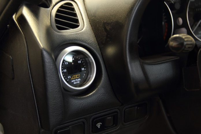
One of the few permitted engine modifications in Spec Miata is the addition of an adjustable fuel pressure regulator, which leans the engine out at higher rpm — well, all rpm — to help it create more power. Racers also are allowed to add an air-fuel ratio gauge to keep an eye on things, although a dyno shop’s instruments are more precise and reliable for tuning purposes.
The good news is that the project isn’t too difficult. I requires no special tools — unless you think a test light is exotic — and can be done in one day if you don’t have a wife, kids, a job, weekend chores, a life outside racing, etc. If you have all that, it takes a bit longer, but it’s an easy project to pick up wherever you leave off if you do it right.
I went with an AEM air-fuel gauge because the company has been in that field for so long. I chose the modified fuel-pressure regulator from 5X Racing and the inline fuel-pressure gauge from Weekend-Racer.com because of their simple approach. It’s also interesting to note the principals of all those companies are NASA racers.
Essentially, you have two projects. One is installing the AFR gauge. The other is installing the regulator, but we’ll treat it as one for the purposes of this story. There will be another story to follow this one on using your new equipment to find more power in the mighty Miata motor, but that’s a feature unto itself.
For now, let’s focus on installing the air-fuel gauge and pressure regulator without hurting yourself or burning down the garage.
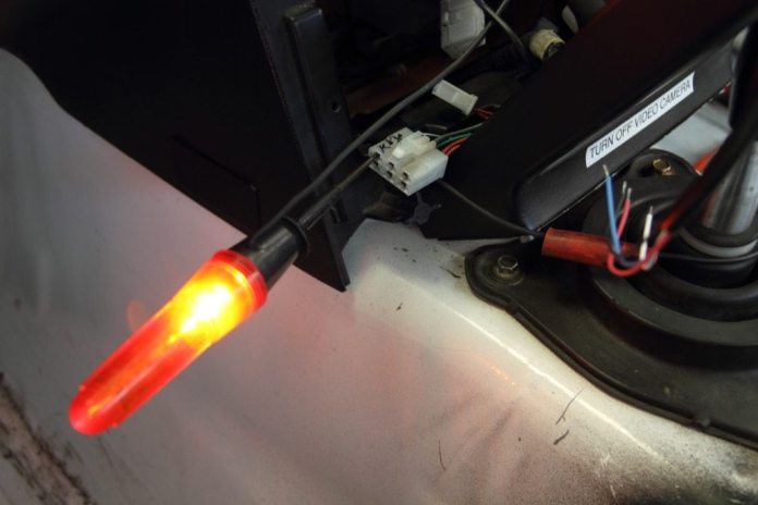
Air/fuel gauges get their signal from a wideband oxygen sensor. The kit comes with a new bung you weld into the existing exhaust pipe. AEM’s bung intrudes very little into the exhaust stream to reduce back pressure and turbulence. I put the new one just ahead of the factory location, offset just a little. Well, my fab guy welded it, not me.The location works because the sensors are accessible from under the hood or inside the wheel opening, yet protected enough to keep them from getting soaked during a rain race.The new AEM wideband oxygen sensor comes with antiseize lubricant already on it. It’s a good idea to put some on the threads of the old sensor, taking due care not to get it on the sensor itself, before reinstalling it.With both sensors in place, you’re ready to reconnect the factory sensor and complete the wiring on the new one.I zip-tied the AEM sensor harness to the left front brake line to keep the wire from contacting the exhaust manifold heat shield.The AEM gauge comes with lots of wiring to fit a variety of cars, so I just looped it several times, tied it with zip ties and fastened it under the clutch slave cylinder so it doesn’t move.The wiring to the gauge goes through a factory opening in the firewall, right next to the speedometer and throttle cables. I covered the wire and the opening with gaffer tape to prevent chafing. You also can see the factory oxygen sensor harness zip-tied out of harm’s way in this photo.With the help of mechanic’s wire, I pulled the gauge connector up through an opening for an air conditioning vent where the gauge will be mounted.The opening for the air conditioning vent is too large to hold the gauge, but if you remove the factory bezel from the vent, it creates a snug fit around the AEM gauge that doesn’t need a retainer screwed to the back of it.Just push it in place for a nice, snug fit and a finished look.I ran the harness over behind the console where there are lots of power sources and ground locations.A test light told me which wires were hot with the key on. I wrote “key” on the connector so I wouldn’t forget which terminal it was.The blue and white wires to the AEM gauge are for data acquisition, so I covered the exposed ends with electrical tape and taped them together to prevent accidental groundings.With the red wire to power and the black one to ground, I fired up the car and, to my surprise, the gauge worked — and there was much rejoicing.And now, on to the fuel pressure regulator, which sits on the fuel rail between the intake and cam cover, right next to the EGR valve. It’s important you don’t have any leaks in this area because the EGR tube is right under the regulator and it’s a hot item.I had some injectors from the old car that were recently cleaned and serviced by Mr. Injector, so I figured I’d install those at the same time. The injector connectors are easier to disconnect if you remove the entire fuel rail first.Remove the three bolts that hold the rail to the head and the connectors are much easier to remove, which is good because they’re easy to break. There are three plastic “pucks” under each bolt. Be careful with them. They’re easy to lose.Here’s what the old fuel rail looks like.Hooray for spares. I had a spare rail with the new regulator all ready to go.Directions from 5X Racing say clockwise for more pressure, counterclockwise for less. I figured I might forget that, so I wrote it on the regulator with a Sharpie.The recently serviced injectors at right looked a bit better than the OEM injectors at left.The factory service manual says to use a little motor oil on the injector O rings so they slide into their ports. It’s also important not to knock any dirt from around the opening into the engine. I used compressed air before I removed the injectors to blow away as much debris as possible.Be sure to plug the feed and return hoses while you’re working on the car because they will drip the whole time if you don’t.Reinstall the injectors and rail and reconnect the harnesses and vacuum hoses.Alert readers will see that the fuel-feed and return hoses are swapped, which is why the car wouldn’t start the first time. Therefore, be sure to mark which hose goes to which pipe on the frame before your disassemble them.The extra hose with the pressure gauge was kind of loose, so I drilled two holes in the neck of the windshield washer bottle and ran a zip tie through them and around the hose. Now it doesn’t move.When you fire it up for the first time, it’s a essential to have a fire bottle on hand. I also hosed down the area with water first, to rinse away any fuel that might have dribbled.With the fuel pressure at the factory setting, it’s time to head to the dyno shop for tuning.


Really great write up!
Excellent write up and illustrations.